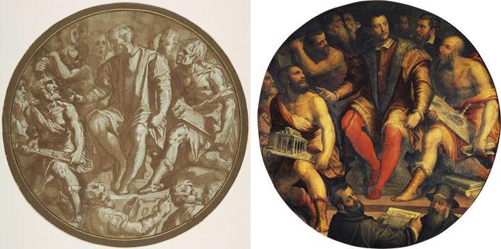
Left: Fig. 1. Attributed to Jacopo Zucchi (Italian, ca. 1540–1596). Grand Duke Cosimo I of Tuscany Surrounded by His Artists, ca. 1556–62. Pen and brown ink, brush and brown wash, highlighted with white gouache, over traces of black chalk or graphite, on gray-green paper, diameter: 9 3/16 in. (23.4 cm). The Metropolitan Museum of Art, New York, Rogers Fund, 1958 (58.104). Right: Fig. 2. Giorgio Vasari (Italian, 1511–1574). Grand Duke Cosimo I of Tuscany Surrounded by His Artists, ca. 1556–62. Oil on wood panel. Salone dei Cinquecento, Palazzo Vecchio, Florence
«The current rotation of works on paper in the Robert Wood Johnson, Jr. Gallery includes a selected group of architectural drawings from The Met collection. The focus of this selection is the complicated relationship between the three-dimensional (spatial) subject matter and the two-dimensional paper medium on which it is represented.»
The size, cost, and scope of most building projects is thus that some form of prototype is needed to create an accurate impression of the end result, to convince investors to commit, and to guide builders in the process of execution. As such, models of various kinds and materials have been in use since Antiquity, but from the Renaissance onward the art of drawing gained significant ground in guiding the design and execution process as an effective and economical medium to communicate the details of a building project among architects, workers, and patrons, and began to engage a growing audience of architectural enthusiasts.
The increasingly central role of drawings is highlighted in one of Giorgio Vasari's round ceiling paintings for the Salone dei Cinquecento in the Palazzo Vecchio in Florence (fig. 2). In it, the artist makes equal use of three-dimensional models and schematic depictions of designs on paper to represent Duke Cosimo de' Medici's cultural patronage in architecture, which formed the nucleus of the civic and political discourse of the period.
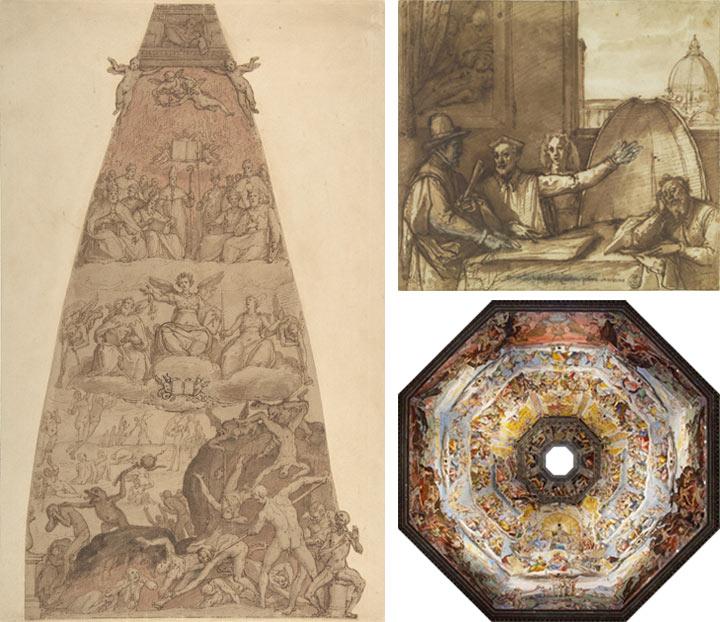
Left: Fig. 3. Federico Zuccaro (Zuccari) (Italian, 1540/42–1609). Scene from The Last Judgment, Study for the Fresco Decoration of One of the Segments of the Cupola of the Cathedral of Santa Maria del Fiore in Florence, 1576–79. Pen and brown ink, brush and brown wash, over red chalk on ecru paper, 17 5/8 x 9 13/16 in. (44.8 x 24.9 cm). The Metropolitan Museum of Art, New York, Rogers Fund, 1961 (61.53). Top right: Fig. 4. Federico Zuccaro (Zuccari) (Italian, 1540/42–1609). Federico Zuccaro Showing the Bozzetto for the Cupola to the Board of Overseers with Giorgio Vasari and Vincenzio Borghini, after 1575. Pen and ink with brown wash. Gallerie degli Uffizi, Gabinetto Disegni e Stampe, Florence. Bottom right: Fig. 5. Interior view of the Dome of the Cathedral of Santa Maria del Fiore, Florence. © Leonardo Pili, 2017
In some cases, a combination of three-dimensional models and drawings was used to create an accurate representation of a large-scale project. This is the case, for example, in the bozzetto, or sketch, depicting the Last Judgment by the renowned artist Federico Zuccaro (fig. 3). The drawing represents the painted decorations for one of the eight segments of Filippo Brunelleschi's dome of the Cathedral of Florence (Santa Maria del Fiore). The drawing was meant to be mounted inside a large three-dimensional model that was to be presented to the board of overseers; an event recorded in another drawing by Zuccaro in which he offers us a clever perspectival view that includes the model in the foreground and the actual dome in the distance (fig. 4).
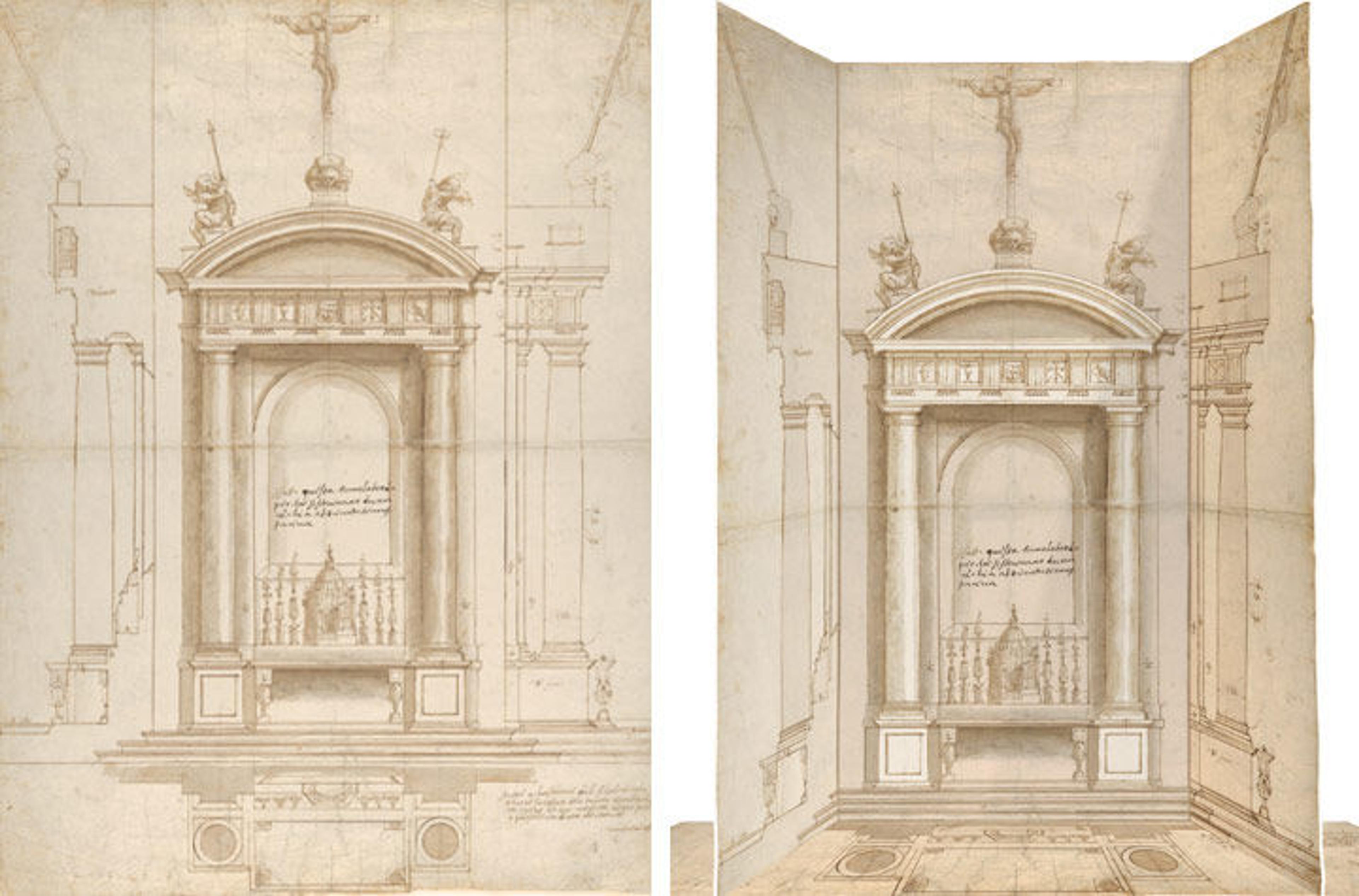
One of the key innovations during the late 15th and 16th centuries, however, was the development of a standardized system of representation that allowed for drawings to function in the same capacity as three-dimensional models. To-scale plans, elevations, and sections were made, and often combined in so-called orthographic projections, as can be seen in the drawing by the noted Florentine sculptor and architect Vincenzo de' Rossi (fig. 6). It is a nearly perfect example of an orthographic representation, combining a frontal elevation, floor plan, side view, and section of an altar that was almost certainly meant for a side chapel in the Roman church of Santa Maria ad Martyres, better known as the Pantheon.
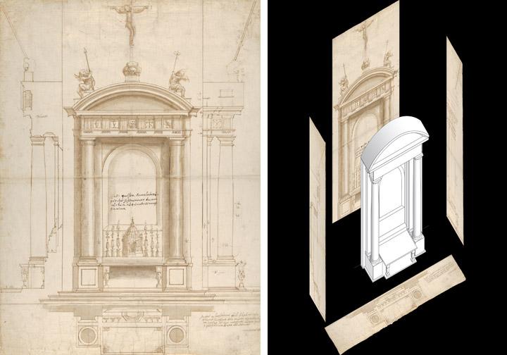
Left: Fig. 6. Vincenzo de' Rossi (Italian, 1525–1587). Design for an Altar Surmounted by a Crucifix in Four Different Views, 1546–47. Pen and brown ink, brush and gray-brown wash over traces of black chalk, ruling, and compass work, sheet: 22 9/16 x 16 3/4 in. (57.3 x 42.6 cm). The Metropolitan Museum of Art, New York, Purchase, Brooke Russell Astor Bequest, 2013 (2013.205). Right: Fig. 7. Digital reconstruction of the altar. © Leonardo Pili, 2017
A comparison with two other drawings from the collection shows how Vincenzo was able to combine information and impressionistic features such as highlights and shading to create a presentation drawing that is neither too abstract—and therefore unable to impress patrons (fig. 8 )—nor too painterly (fig. 9), which causes the drawings to lose much of its functional value.
Reading all the information that is given in this type of drawing requires a trained architectural eye. For the purpose of our display at The Met, we were assisted by Leonardo Pili, who created digitally enhanced reconstructions to visualize the projects in three dimensions. In the case of Vincenzo de' Rossi's design for an altar, the reconstruction beautifully underlined the meticulous execution of the orthogonal scheme. The implicit three-dimensionality allows it to be folded into a box-like structure to functions as a miniature model of the altar (fig. 7).
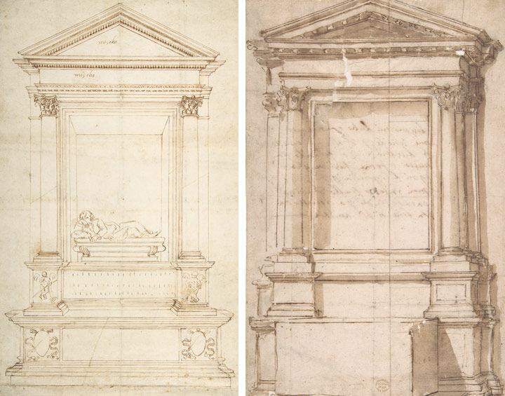
Left: Fig. 8. Anonymous, Central Italian, 16th century. Design for a Wall Tomb, ca. 1524. Pen and brown ink, over stylus-ruled and compass-incised construction marks, on light tan laid paper, 14 3/8 x 9 1/16 in. (36.5 x 23 cm). The Metropolitan Museum of Art, New York, Edward Pearce Casey Fund, 1998 (1998.254). Right: Fig. 9. Anonymous, Central Italian, 16th century. Architectural Frame for Altar, ca. 1550–80. Pen and brown ink, washed, 12 1/2 x 8 in. (31.8 x 20.3 cm). The Metropolitan Museum of Art, New York, Gift of Cornelius Vanderbilt, 1880 (80.3.593)
The digital reconstructions make clear how the systems of representation that were developed for architecture caused the lines between the two-dimensional drawing and the three-dimensional model to blur, and make it easier to understand how one could even replace the other at times. A stunning example is the drawing attributed to the artist known as Il Cigoli after a design by the Medici court artist Bernardo Buontalenti (fig. 10). It shows an idea that was to be submitted in the 1589 competition launched to choose an architect for the decoration of the facade of the Cathedral of Florence, which had been left unfinished. Cigoli's detailed orthographic rendering, with its studious attention for light and shade and the realistically colored marbles, easily rivals contemporary three-dimensional models such as Buontalenti's own wooden mock-up for a later, slightly altered version of the same design (fig. 11).
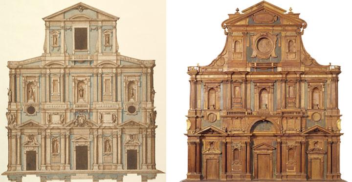
Left: Fig. 10. Attributed to Cigoli (Ludovico Cardi) (Italian, 1559–1613), after Bernardo Buontalenti (Bernardo delle Girandole) (Italian, ca. 1531–1608). Drawing for Buontalenti's Model for the Facade of Santa Maria del Fiore of Florence, 1589. Pen and brown ink, brush with brown and blue-green washes, sheet: 16 1/2 x 15 in. (41.9 x 38.1 cm). The Metropolitan Museum of Art, New York, Gift of Herbert Mitchell, 1966 (66.510). Right: Fig. 11. Bernardo Buontalenti (Bernardo delle Girandole) (Italian, ca. 1531–1608). Wooden Model for the Facade of the Cathedral of Santa Maria del Fiore in Florence, after 1589. Museo dell'Opera del Duomo, Florence, Modello 132
In certain cases it is difficult to make sense of what an architectural drawing represents without mentally (or physically) folding it to understand it in three dimensions. This is the case, for example, with two very different drawings representing details of the decoration schemes of Italian Baroque palaces (figs. 12, 14). The first drawing depicts the elevation of a wall, but only by folding and curving the paper do we discover that it actually seamlessly continues into the vault and lunettes (fig. 13). In addition, only a quarter of the room is actually represented, but the opportune placement of mirrors would have easily doubled the image, demonstrating the projected space in its entirety to a patron without necessitating a complete drawing.
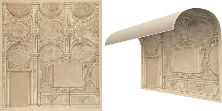
Left: Fig. 12. Anonymous, Italian, 18th century. Design for a Wall and Ceiling with Frames and Decorations in Stucco, ca. 1690–1710. Black chalk, pen and brown ink, brown wash, sheet: 15 9/16 x 14 7/16 in. (39.5 x 36.7 cm). The Metropolitan Museum of Art, New York, Purchase, Brooke Russell Astor Bequest, 2013 (2013.210). Right: Fig. 13. Reconstruction of the architectural space. © Leonardo Pili, 2017
The decorative project for the lowered vault of a palace interior (fig. 14)—which seems rather broken up at first glance—can be manipulated in a similar manner by cutting along the drawn borders of the architectural design and subsequently folding the sheet 90 degrees along the vertical axis to form an angle, and curving the upper part of the sheet along the edge to create the vault (fig. 15).
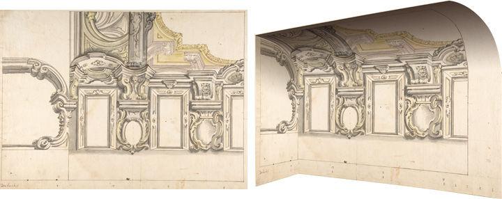
Left: Fig. 14. Anonymous, Italian, Piedmontese, 18th century. Design for an Attic Window and an Interior, with the Frame of the Ceiling Shown, 1700–1780. Pen and brown ink, brush with gray, brown and yellow wash, over lead point or graphite, 13 11/16 x 18 7/8 in. (34.8 x 48 cm). The Metropolitan Museum of Art, New York, Gift of Leon Dalva Sr., 1965 (65.654.63). Right: Fig. 15. Reconstruction of the architectural space. © Leonardo Pili, 2017
Architects could pack even more information into a drawing by creating a design with variants. The geometric view below (fig. 16) details three different schemes for the execution of a cross vault or dome with an oculus (a round window open to the outside air), possibly to be executed in trompe-l'oeil. As in the previous drawings, only part of the building is depicted, but here the design cannot be completed simply by folding and adding mirrors, since we are dealing with the three variants included by the architect at center left, center right, and in the right segment. Thanks to the digital reconstructions of Leonardo Pili, we are able to "unpack" this information and create three different prospects of what the vaults would look like after the patron had chosen his favorite decoration scheme.
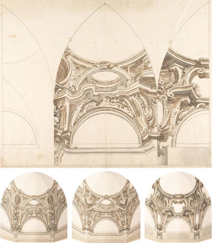
Top: Fig. 16. Anonymous, Italian, Piedmontese, 18th century. Three Designs for the Decoration of a Vault or Dome, 1700–1730, Pen and brown ink, brush with gray and brown wash, over lead point or graphite, with ruled and compass construction, 14 5/16 x 20 3/16 in. (36.4 x 51.2 cm). The Metropolitan Museum of Art, New York, Gift of Leon Dalva Sr., 1965 (65.654.14). Bottom: Figs. 17a–c. Reconstructions of the three different options for the decoration scheme. © Leonardo Pili, 2017
But what to do when the drawing itself is three-dimensional? Among the drawings selected for the rotation is a multi-layered floor plan of the two courtyards inside the famous Villa Giulia (fig. 18). This suburban pleasure villa was built on the outskirts of Rome by Pope Julius III between 1550 and 1555. The building was based on designs by the architect Jacopo Vignola with revisions by Bartolomeo Ammanati and Giorgio Vasari, as well as probable advice from Michelangelo.
Due to this "dream team" of architects and its original design, the building became legendary almost as soon as it was finished. This fact is underlined by our drawing, which is a survey done after the existing structure by an unidentified French artist, rather than a design by one of the architects involved in its creation. In the survey, the draftsman has attempted to visualize the relationship among four distinct levels of the building by superimposing several layers of drawings hinged together along the borders. It represents an impressive effort to make architecture transportable and acquaint people in other cities and countries with this celebrated Roman building.
This, or a similar drawing, may also have formed the base for printed images of the Villa's floor plan, which we find alongside a perspectival elevation of one of the courtyards, among the prints published in the context of Antonio Lafreri's Speculum Romanae Magnificentiae (figs. 19, 20).
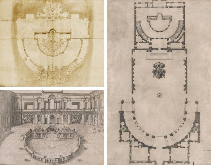
Top left: Fig. 18. Anonymous, French, 16th century. Villa Giulia, Plan, ca. 1550–80. Pen and dark brown ink, brush and brown wash, over traces of black chalk, ruling and compass work, on a gathering of five sheets of paper, 23 1/4 x 16 1/4 in. (59 x 41.3 cm). The Metropolitan Museum of Art, New York, Gift of Janos Scholz and Anne Bigelow Scholz, in memory of Flying Officer Walter Bigelow Rosen, RCAF, 1949 (49.92.73). Bottom left: Fig. 19. Anonymous. Plan of (Part of) the Villa Giulia, with the Arms of Pope Julius III Engraved at the Center, from the Speculum Romanae Magnificentiae, ca. 1550–80. Engraving, sheet: 18 7/8 x 13 3/8 in. (48 x 33.9 cm). The Metropolitan Museum of Art, New York, Rogers Fund, Transferred from the Library, 1941 (41.72[3.37]). Right: Fig. 20. Anonymous. View of the Courtyard within the Villa Giulia in Rome, from the Speculum Romanae Magnificentiae, ca. 1550–80. Engraving, sheet: 13 5/8 x 18 1/8 in. (34.6 x 46 cm). The Metropolitan Museum of Art, New York, Rogers Fund, Transferred from the Library, 1941 (41.72[3.52]).
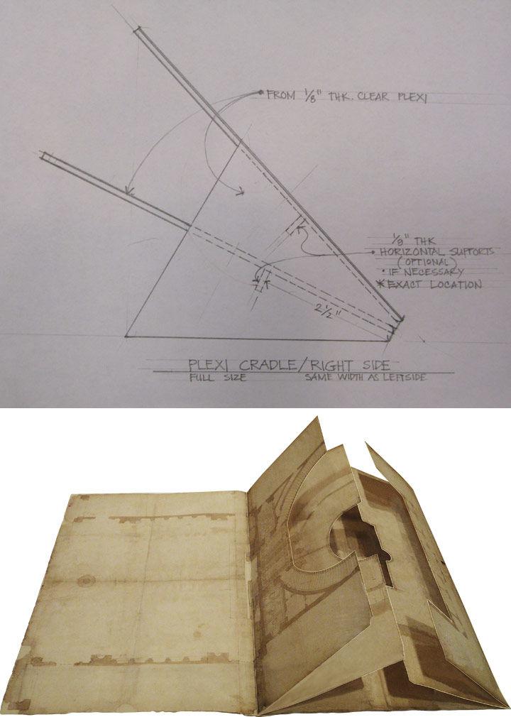
Top: Fig. 21. Working drawing for the production of a custom Plexiglas stand for the Villa Giulia drawing. © Ricky Luna, 2017. Bottom: Fig. 22. Reconstruction of the layers of the drawing "opened up" by the Plexiglass stand. © Leonardo Pili, 2017
To be able to install this intricate drawing in the Robert Wood Johnson, Jr. Gallery, our department's drawings technician, Ricky Luna, also turned to the paper medium to design a three-dimensional support structure to display this drawing in a manner that allows our visitors to explore its various layers without causing too much stress to the 400-year-old paper model (figs. 21–23).
This drawing, and the other architectural designs discussed in this post (except for figures 8 and 9), are on view in gallery 690 through November 20.
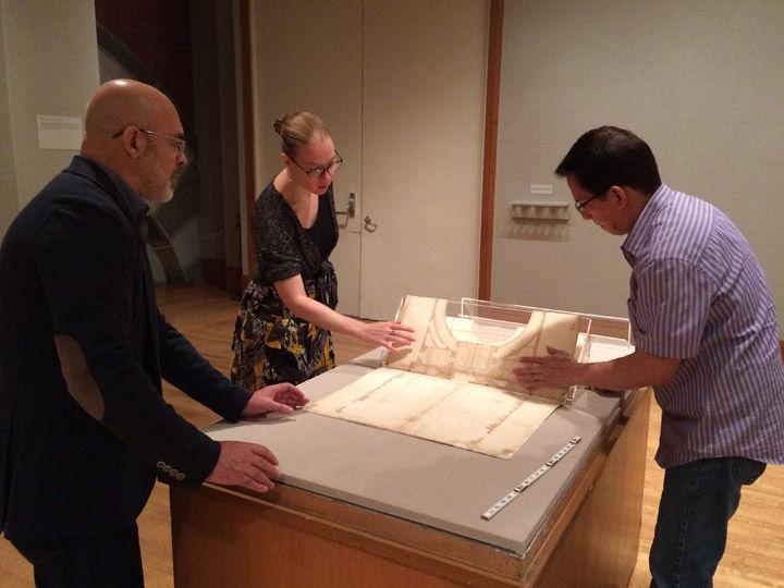
Fig. 23. Installation of the Plan of Villa Giulia in gallery 690. Photo courtesy of the authors
The authors would like to thank Leonardo Pili and Ricky Luna for their indispensable help in making legible these fascinating architectural designs from the Department of Drawings and Prints.
Related Links
Drawings and Prints: Selections from The Met Collection, on view at The Met Fifth Avenue through November 20, 2017
MetPublications: Femke Speelberg and Furio Rinaldi, "Vincenzo de' Rossi as Architect: A Newly Discovered Drawing and Project for the Pantheon in Rome," Metropolitan Museum Journal 50 (2015): 163–178.